Mechanical design · Manual J, S & D
How we design HVAC systems
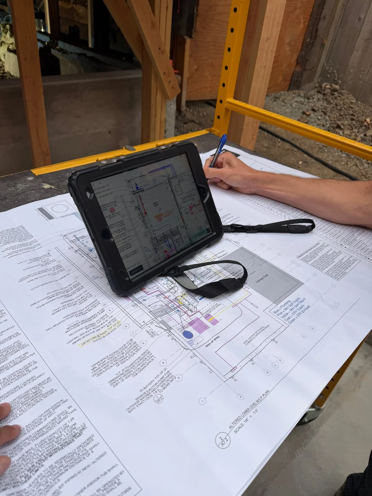
Every residential system we install is designed in-house from the project drawings: a Manual J load calculation, a Manual S equipment check and a Manual D duct design.
Case study
Hillside remodel, Berkeley
A whole-house remodel on a three-level hillside lot, conditioned with a mix of ducted and ductless heat pump equipment. What follows is the design as it was done, in the order it was done.
- Location
- Berkeley hills
- Conditioned area
- 2,269 ft², 3 levels, 18 rooms
- Design load
- 34,307 Btu/h heating 30,503 Btu/h cooling
- System
- Mitsubishi multi-zone heat pump, 3 indoor units
The house, traced from the drawings
The load model is built on top of the architectural sheets. Each room is drawn at scale on its own level, with walls, windows and doors placed where the plans show them. Assemblies come from the plans and the Title 24 report, not defaults.
- Levels
- Basement, first, second
- Glazing
- By orientation, with overhangs and shading
- Envelope inputs
- Plans and Title 24 report
A load for every room
The output is a room-by-room table of heating, sensible and latent cooling, and airflow. That table drives the equipment check and every duct size that follows.
- Heating
- 34,307 Btu/h
- Cooling
- 30,503 Btu/h
- Design airflow
- 1,358 CFM
- Sensible heat ratio
- 0.97
Equipment checked at design conditions
Nameplate tonnage is rated at test conditions, not the job’s. We use the manufacturer’s expanded performance data at the design temperatures and compare capacity with the load, for the whole system and for each indoor unit.
- Outdoor unit
- MXZ-SM48NL
- Total cooling
- 131% of design load
- Indoor units
- 2 SVZ air handlers, 1 PEAD ducted
- Heating
- Checked at winter design temperature
Ducts sized from the blower out
Duct design starts with the air handler’s available static pressure. Coil, filter and grille losses come off the top, the longest run sets the friction rate, and every trunk and branch is sized from it.
- Available static
- 0.41 in. w.c.
- Design friction rate
- 0.171
- Supply trunk
- 28×8, 1,375 CFM
- Branches
- 4" to 9"
For GCs and architects
What the design gives the project
Mechanical problems found in framing are expensive. A finished design before permit moves those decisions back into the drawings.
Space held in the drawings
Air handler locations, duct sizes, chases and return paths are known during design development, so soffits and framing are sized for them.
A defined system to price
Equipment, capacities and duct sizes are on paper before bidding, so the mechanical scope is the same for everyone pricing it.
Documents for plan check
Manual J, S and D reports that match the Title 24 compliance documents, and answers to reviewer comments on them.
Designed by the installing team
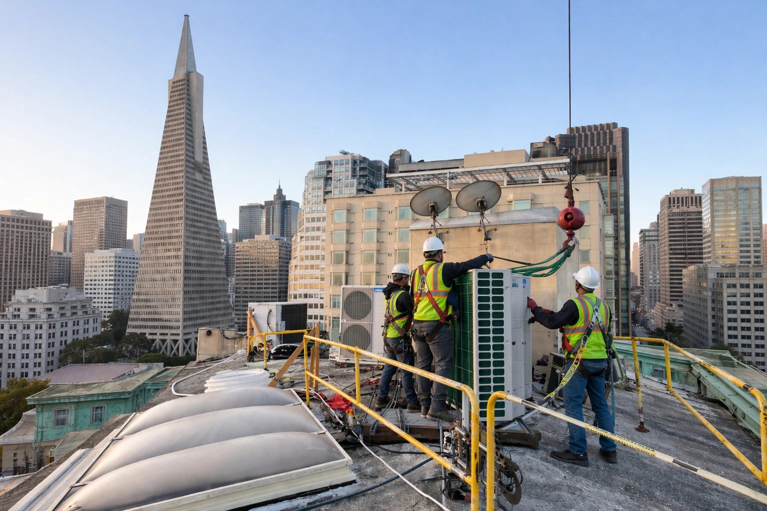
The people who size the system install it, so the design accounts for where equipment and line sets can actually go.
Timing
When to bring us in
- 01
Schematic design
Rough loads and a system type, so the architect can plan equipment locations and the GC can carry a realistic budget.
- 02
Design development
Full Manual J, S and D from the developing set. Duct routes, chases and electrical loads go back to the design team.
- 03
Permit set
Final reports issued with the permit drawings, and revised if the plans change during review.
See also: working with general contractors, working with architects, Manual J, S & D for homeowners, and our notes on why load calculations matter and why duct sizing matters before installation.
Project inquiry
Talk through a project
Send the drawings or describe the project, the phase it is in and the system you are considering. We review every inquiry and reply directly.
- Phone
- 510-399-4090
- team@3rdgen.io
- Shop
- 1230 4th St, Unit A, Berkeley
Project Inquiry
Inquiry Sent
Thanks — your project details are on their way to 3rdGen. We’ll review them and follow up about the next step.